To output the results from TopoGX use the File->Save As... menu option.
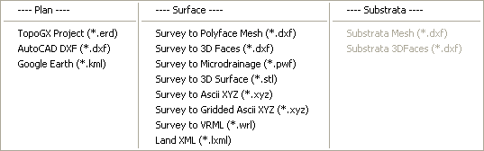
The menu is categorised into four type of output file. The choices are as follows:
This is the file format used natively to store all details and data of the drawing and design model. When an ERD file is re-opened it will show the project exactly as it was when you saved it.
The DXF file format can be read by most other CAD related software applications.
This is the Autodesk format for drawing exchange.
When you select this option you will get a preview window with a few optional settings.
When you open the *.kml file with Google Earth it will zoom into the location which matches the coordinates of your drawing.
This is very useful for visualising exactly where a survey drawing is situated within the UK.
At the present time, the lat/lon positioning will only be accurate when the drawing is at UK Ordnance Survey coordinates.
This is a facility for producing simple coordinate data in CSV files representing one of the designed features (for example, a road centreline, or a channel line). The format is suitable for reading directly into the setting out devices on site. When this output option is selected you will be prompted to choose a design line from the drawing, which is to be written to the CSV file.
This file format is compatible with popular GPS devices, and can also be loaded by Google Earth. The output GPX file will contain only the designed road lines.
This option produces a DXF file containing the longsection drawings from all of the roads in the design. The longsections are displayed one below the other in the DXF drawing. Each one is drawn up as it would be shown in the vertical alignment view for the road.
This DXF output file contains just the 3D triangulated surface represented as a Polyline mesh. You will find this useful if your application requires a pre-triangulated 3D surface, and can import a polyline mesh.
This DXF output file contains just the 3D triangulated surface represented as 3D FACE entites. You will find this useful if your application requires a pre-triangulated 3D surface, and can import 3D Faces.
This file format is suitable for loading into the popular drainage design and simulation application. Although Microdrainage is capable of importing a DXF itself, it can be poor at triangulating the DXF data into a ground surface. However, Microdrainage can import pre-triangulated surface data as a PWF file. It can then obtain accurate ground levels from this surface.
The STL format is used by some 3D modelling systems and 3D printers. The output represents the 3D ground surface, extruded to a thickness appropriate to the site size.
This output option will produce a text file containing the X,Y and Z coordinates of all the 3D items in the drawing. It contains only points (no lines).
This option produces an ascii file of XYZ coordinates at a regular grid spacing, representing the 3D ground surface. This type of regular grid data is sometimes referred to as a DEM (Digital Elevation Model) or a DTM (Digital Terrain Model). Whent he option is selected you are first prompted to specify the desired grid spacing.
This option produces file containing Virtual Reality Markup Language (VRML) represening the 3D surface model.
When substrata have been used in the project this option is available to output them to a DXF file in the form of Polyline Mesh entities.
When substrata have been used in the project this option is available to output them to a DXF file in the form of 3D FACE entities.