To see the list of drawing layers for the active project click the ![]() Layers toolbar button at any time.
Layers toolbar button at any time.
Also, most right-click menus in the drawing windows include a Layers option. 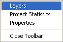
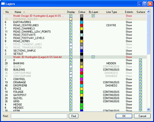
The Layers Window displays the layers for all the models in the active project. For example, one model may be a ground survey you loaded from a DXF file, and another may be an architect's indicative layout you've imported from another file.
Any design work you've done will be in the first model in the list. The different models are indicated by different background shades in the list, and the name of the model is shown in red text on a row preceding the list of layers for the model. The current ground survey model is shaded with a light green background.
Layer information is shown under various column headers:
The layers number indicates the ordering the layers were found in the orginal data file, or else the order the new layers were added to the project. To order the list by number, simply click the column header.
The layers name is shown as was given in the orginal data file, or else as assigned by TopoGX. To order the list by name, simply click the column header.
Each layer has a tick-box indicating whether it is currently displaying on the plan view window. You can click on the tick-box to change the display state of a layer. The plan view of the project will instantly update to show the difference of toggling the layer on or off.
A coloured box is shown for each layer. This indicates the colour for the items which are on that layer.
This colour is used when the ![]() Survey Colours toolbar button has been selected.
Survey Colours toolbar button has been selected.
You can click on the layer's colour-box to select a different colour for it.
There is a tick-box in the By Layer column for each model (not for the model's layers). When the By Layer box is ticked then the layers indiviudal colours are used for drawing the items which are on it. When the By Layer box is not tick then the one colour in the Colour column is used for drawing all the layers (and the individual layers colours for the model are ignored).
By default each imported model is drawn in a grey colour, and this makes it easy to see which model is which on the plan view, and highlights the designed items which are in non-grey colours.
If the items on a layer are drawn with a particular line type then that will be indicated under this column.
The word Show appears under this column for each layer. If you click the mouse on the word Show then a rectangle will flash on the plan view indicating a bounding bound around all the items which appear on that layer. This can be very useful for finding a layer on the drawing.
Each layer has a tick-box indicating whether it is currently used in the 3D surface for the model. Initially, layers that are ticked under the Display column are also used for the 3D surface. You can click the tick-box under the Surface column to toggle layers on or off for the 3D surface. The effect is shown instantly on the 3D View window (and on the Plan View window if Survey Height Shading is in effect).
For example, your survey may include overhead power lines which are levelled higher than the ground surface. These lines would be undesirable in the 3D surface so you can untick their layer in the Surface column. However, you can still have the power lines displayed in the drawing by keeping the tick-box in the Display column.
Each row in the list has a right-click menu which shows relevant options, depending on whether the row is a model name or layer, and what type of model it is (e.g. design mode, ground surface model, etc.)
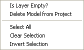
When you select the Is Layer Empty? option the model data will be checked to determine if the layer is used by any item. If it is found that no item references the particular layer then you will be given the option to delete the layer from the model.
Any model that is not the design model or the current survey may be deleted from the project. This can be useful for clearing out models that you once loaded into the project but now no longer require.
If you want to retain a model in the project but have it not shown in the drawing, then simply de-select the Display box on the model name row.
The Set As Current Survey option is offered for any model which is not the design model or the current survey model. Selecting this option will set this model as the one used for the ground surface. The current ground surface is the one shown by default in the 3D View window, and all design work is done relative to its levels.
This option will heighlight all the models and layers in the list. This can be very useful when you want to modify a property of all (or nearly all - de-select individual layers by holding the Ctrl key when clicking with the mouse). For example, you can select all layers and then click one of the Display boxes to turn them all on or off on one go.
The Invert Selection option is very useful for selecting all but one or two layers. For example, if you want to turn of everything except for one particular layer, then first select that layer, use the Invert Selection option, and then then click one of the Display boxes on a selected layer to turn them all off in one go.
The Clear Selection option de-selects all rows so that nothing is selected. It does not remove any model data, or make any other change.