This facility calculates the volume between two surfaces.
Note: Before using this facility you will need to have more than one surface model in the project. You may have loaded the first surface when you started the project by opening a ground-survey (for example, from a DXF file). Additional surfaces can be added to the project using the Import option on the File menu.
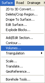
To use the surface volumes facility click the Surface menu at the top of the screen.
Select the Volumes... option.
The following window is displayed for selecting the two surfaces for the volume calculation:
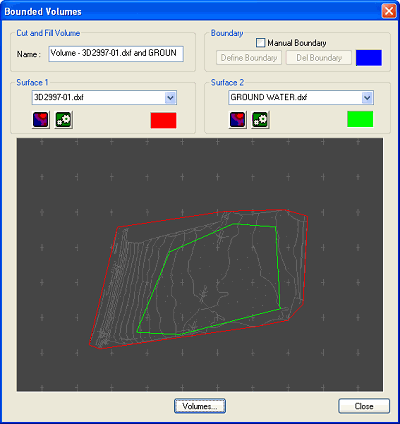
Select each of the two surfaces from the drop-down list of available surfaces. Surface 1 is displayed on the preview with a red boundary. Surface 2 is displayed with a green boundary.
Click the Volumes... button to see the Cut and Fill volumes calculation result.
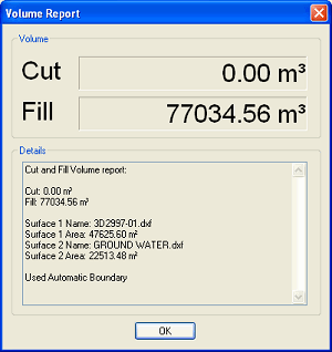
The Cut volume is where Surface 2 is lower than Surface 1.
The Fill volume is where Surface 2 is higher than Surface 1.
The volumes calculated by TopoGX are the exact geometrically calculated volumes between the two surfaces. TopoGX does not use approximate voluming methods.
By default a boundary is calculated which includes the overlapping areas of the two surfaces. If one surface is entirely contained withn the other, then the boundary is that of the smaller surface.
You may want to specify your own boundary for the volume calculation. In this case select the Manual Boundary checkbox and click the Define Boundary button.
When you click the Define Boundary button the main plan-view window is shown prompting you to click around your required boundary with the mouse. As you click, the boundary line will be shown in blue. The boundary must be within the extents of both surfaces. Use the Undo button if you mis-place a point and want to redo it. Right click and quit when you have finished and the Bounded Volumes window will reappear showing the defined boundary.
To view some properties of each of your two selected surfaces click the ![]() surface properties button.
surface properties button.
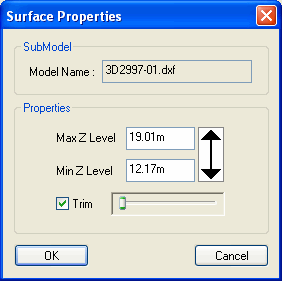
The Surface Properties window shows the maximum and minimum levels of the surface. This can be useful for verifying which is in Cut and which is in Fill.
You can modify the maximum and minimum levels which are used for the surface. Restricting the level range can be used to exclude high or low drawing features from the surface. This will often reduce the outer boundary line, but it will not produce holes inside the surface.
By default the two surfaces are shown with untrimmed boundaries, providing the maximium available surface area for the overlap of the two surfaces. However, often the outer boundary will stretch across areas at the edge of the surface which contain no levelled drawing features. You can use the Trim slider to increase the trimming of the surface boundary to exclude unlevelled areas.
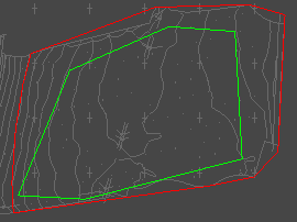
Surface 1 (red boundary) untrimmed
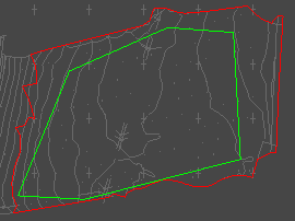
Surface 1 trimmed