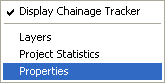
To access the Project Options window click the right mouse button in the main plan view and select the Properties option from the menu.
The Project Options window shows general properties for the project and some options for display of the plan view working area.
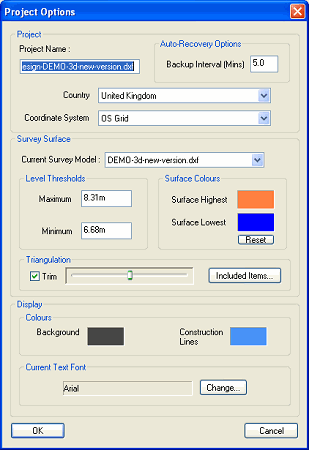
The project name will default to the name of the original file from which the project was first initiated. You can change the project name to be something more descriptive.
The project name will appear on the Layers window as the name for the design model.
In case of any event which might result in your project not getting saved (for example, if there is a power failure, or if your computer unexpectedly reboots itself) the program automatically saves itself at regular intervals.
By default it is every 5 minutes. This means the most work you might ever lose is five minutes worth. You can specify how often the automatic saving occurs.
When the automated save occurs you may see the progress bar along the bottom of the main program window for a second or two.
Sometimes, when large quantities of data have been loaded into the project, the saving operation can take several seconds. While the save is taking place the program will not allow any user operations (because changing the project mid way through a save would lead to a corrupted file). If you find this temporary interruption is occurring too often for you, then you might consider changing the Backup Interval to a longer period.
Whenever you open a project TopoGX will detect if there is a recovery file which is newer than the project file (indicating that some disaster may have previously occurred preventing normal saving of the project).In this case you will be offered the choice of recovering the project.
You can specify which coordinate system you are working in. Many countries have a number of different coordinates systems for different regions (for example, in the USA there are over one hundred State Plane Coordinate systems.
To select your coordinate system, first select your Country from the drop-down list. Then select your Coordinate System. The list of coordinate system choices on the drop-down is appropriate for the chosen country.
The chosen coordinate system identifies where in the world your site is located. This is beneficial when you want to use the KML output facility to view your site on Google Earth.
There will usually be a number of different 2D and 3D models loaded into a project. For example, a survey ground model, an architect's proposed layout drawing, and maybe surrounding map data.
By default, TopoGX assumes the ground survey is the first file that was loaded when the project was initiated. This may not always be the case, and you can easily specify which model is your ground model here.
Note: The current survey model can also be set on the Layers window.
When TopoGX creates a 3D surface from the current survey model, it analyses all the drawing features and works out the useful level range. It automatically excludes any anomalous levels which appear to be either a surveying error, or perhaps something like an overhead power line (which should not be part of the ground surface).
If you want to increase or decrease the level range which is used for the 3D surface then you can alter the Maximum or Minimum levels. The result is shown (for example, on the 3D View) as soon as the OK button is pressed.
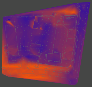
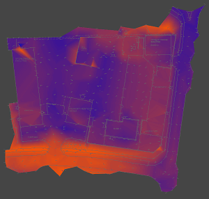
When using the Survey Height Shading facility the Plan View represents the survey surface heights as smoothly grading colours to indicate high levels through to lowest levels.
By default the colour scheme is bright orange for highest levels, grading through to dark blue for lowest levels. You can change these two colours by clicking on the corresponding colour patch on this options window. The result is shown instantly on the Plan View window (if Survey Height Shading is in effect). You can use the Reset button to revert back to the orange-blue scheme.
The 3D surface of the current survey model is actually made up of a mesh of triangles (called a triangulation).
Normally the triangles are not shown, but if you want to see them use the Show Triangles Wire Frame option on the View menu. If you also turn on the Survey Height Shading you'll see that some of the triangles at the edge of the site are not used for the surface. This is because they are beyond the extent of the surveyed information. Levels interpolated between items at the edge of the site would be an approximate guess of what ground feature might be in these unsurveyed regions.
|
|
| No trimming | Automatic trimming |
TopoGX automatically trims off triangles which would stretch over unsurveyed regions at the edge of the site. You can control how much trimming occurs at the site boundary by moving the slider bar next to the Trim option. The result is shown instantly on the Plan View and the 3D view.
If you want no trimming at all, then deselect the Trim check-box.
By default certain drawing entities are not used for making the 3D ground surface. For example text entities rarely have useful surface level values. However, there may be cases where you specifically want to include these other drawing items, or disclude more common drawing entities.
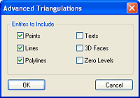
Sometimes a surface may have already been triangulated by some other system, and all you've been sent is the set of triangles in the form of a mesh of 3D faces. If this is the case, you can select the 3D Faces check-box so that they are included in the ground surface for your design model. Normally, 3D Face entities are ignored because the original information from which they were created is usually supplied as well, and TopoGX will normally make a better job of forming the triangulated surface than other systems.
Normally levels of exactly zero are ignored for the ground surface because zero is often used to represent an unlevelled feature. However, if your site spans the zero height range then you may decide that an item at exactly zero level is in fact a true level. To include the zero levels in the ground surface select the Zero Levels check-box.
The background colour of the plan view drawing is usually dark. Some people like it completely black for high contrast, whereas other people like it dark grey to reduce eye-strain. Sometimes you may want to set the drawing background to white so that you can see what it would look like when printed on white paper.
To change the drawing background colour click on the background colour patch.
Note: A RGB (red,green,blue) of 70,70,70 is thought to be good for reducing eye-strain.
When the background colour is dark then drawing features that are grey-shades will be inverted in intensity so as to show up against the background colour. In other words, black lines are drawn in white on the screen.
The line colour used for displaying contruction lines can also be changed by clicking on the Construction Lines colour patch.
In the Plan View text items are all rendered in the same font. By default the Arial font is used. You can select any font which is available on your computer by clicking the Change... button next to the current text font name. (Note: When text is shown at very small size on screen it is always shown in Arial font regardless of what is selected here).